LED Walls for Trade Shows: A 4-Step Guide
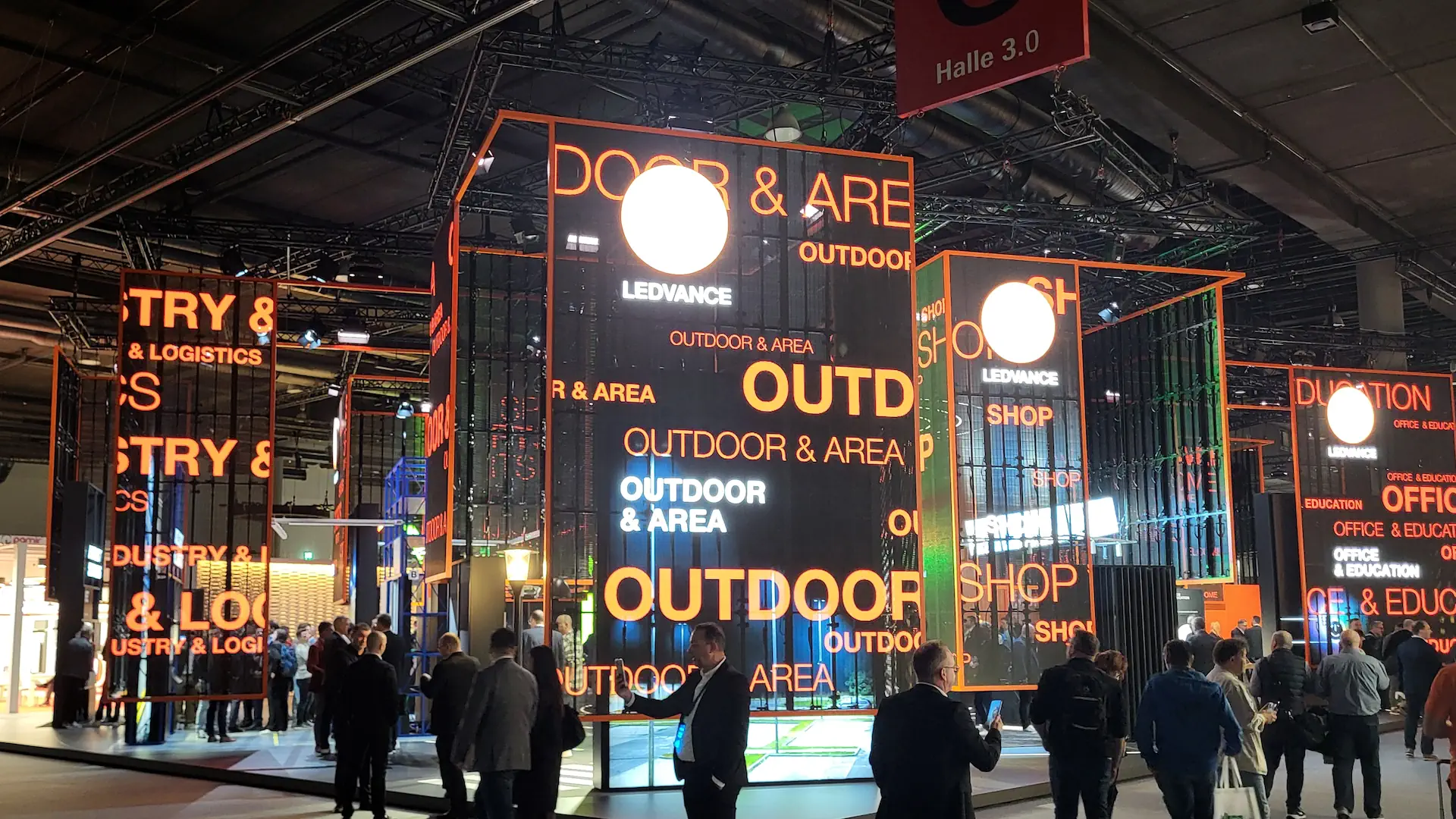
There’s that one magical moment at every trade show: The hall lights dim gently, the first visitors stream through the aisles, and suddenly your booth glows with colors so brilliant that even the coffee cup in the marketing director’s hand reflects them. A professional LED wall is no longer just a visual element—it is the pulsating visual centerpiece of a modern brand presentation. But when glowing semiconductors collide with the harsh reality of the trade show, millimeters, nits, and amperes determine the difference between a cinematic brand presentation and an embarrassing pixel failure.
Anyone who has ever experienced how an incorrectly calculated electrical load blew the fuses in half the exhibition hall, or how an inappropriate pixel pitch turned a lovingly produced promotional video into a coarse-meshed flyscreen, knows: LED technology is a fusion of advanced engineering and uncompromising physics. It’s all about thermal dynamics, precise rigging calculations, sub-millimeter tolerances in module locking, and color space calibrations that even seasoned colorists rave about.
This technical guide walks you through the process—expertly, thoroughly, and with just the right touch of industry charm. Whether you’re an AV designer calculating the final safety margins, an exhibition stand builder looking for seamless curves, or a marketing manager aiming to get the most out of your budget: We shed light on the physical and architectural factors and show you, step by step, how to set up your LED wall so it’s technically flawless and visually stunning.
Precisely Calculate Pixel Pitch and Viewing Distance
The pixel pitch—that is, the center-to-center distance between two adjacent LEDs in millimeters—is the fundamental parameter of every LED wall. It not only determines the physical resolution of the display but also directly influences the cost structure and the visual experience of your visitors. A smaller pitch means more diodes per square meter, a higher pixel density, and consequently a razor-sharp image even at close range. However, if you stand too close to a screen with a pitch that’s too large, the human eye can make out the individual pixels: The image breaks down into a distracting grid, and the dreaded moiré effect distorts perception. From a technical standpoint, it is therefore essential to harmoniously align the threshold of visual acuity (the so-called visual acuity limit of the eye) with the geometric module structure.
In event technology, the following formula has become the golden rule of thumb for the minimum viewing distance: Minimum distance (in meters) = pixel pitch (in mm) × 1.0 to 1.5. With a pixel pitch of 2.6 mm, the pixels begin to blend together seamlessly at a distance of approximately 2.6 to 3.9 meters. When displaying text, complex CAD visualizations, or high-resolution 4K content loops, the balance tends to shift toward the factor-1 value. The physics behind this is based on the resolving power of the human retina, which, at a normal visual acuity of 1.0, perceives two points as separate when their angular separation is approximately one arcminute or greater. If the viewer gets closer than this distance, the structure of the SMD or COB LEDs becomes visible, which instantly destroys the visual immersion.
At the trade show booth, this calculation must be carefully aligned with the booth design and the traffic flow areas of the exhibition hall. If the LED wall is positioned directly at the edge of the aisle, where passersby walk by at a distance of just 1.5 meters, a fine-pitch system with a pitch of less than 1.8 mm is mandatory. If, on the other hand, the wall is mounted as an imposing headline feature four meters above the double-decker and faces the audience in the main aisle, an ultra-high-resolution 1.2-mm pitch would be astronomically expensive overkill. Here, you’re wasting valuable budget that could be invested in better content or adaptive lighting. The art of professional AV planning, therefore, lies in precisely mapping the target audience’s primary field of view and tailoring the pixel pitch to it with pinpoint accuracy.
Reference Matrix: Pixel Pitch, Resolution, and Viewing Distance
| Pixel pitch (mm) | Min. viewing distance | Optimal viewing distance | Density (pixels/m²) | Typical applications |
|---|---|---|---|---|
| 0.9 mm (COB/Micro-LED) | approx. 0.9 m | 1.5–2.5 m | 1,234,567 | High-end control rooms, luxury trade show booths, close-range displays |
| 1.2 mm (fine pitch) | approx. 1.2 m | 2.0–3.5 m | 694,444 | Exclusive indoor lounges, detailed presentations, text screens |
| 1.5 mm / 1.8 mm | approx. 1.5 – 1.8 m | 2.5 – 4.5 m | 444,444 / 308,641 | Elevated exhibition booth, close to the main aisles |
| 2.6 mm (Standard Event) | approx. 2.6 m | 4.0 – 7.0 m | 147,928 | The Classic: Main exhibition walls, stage backdrops, keynote presentations |
| 3.9 mm (Outdoor/Indoor XL) | approx. 3.9 m | 6.0 – 10.0 m | 65,536 | Large festival stages, long-range coverage, outdoor areas, indoor ceilings |
Comparing LED Modules: 1.5 mm vs. 2.6 mm Pitch
When it comes to selecting specific modules for professional trade show construction, the final decision surprisingly often boils down to a choice between “1.5 mm and 2.6 mm.” The 1.5 mm pitch represents the fine-pitch panel class and primarily uses highly advanced SMD (Surface Mounted Device) LEDs or state-of-the-art COB (Chip-on-Board) technology. With COB, the bare LED chips are bonded directly to the circuit board and sealed with a protective resin layer. This ensures dramatically greater break resistance along the module edges, deeper black levels, and outstanding contrast ratios. This design is the scalpel of the screen world: finely tuned, precise, and perfectly suited for displaying delicate typography, intricate UI interfaces, or detailed product displays without visible stair-step effects.
On the other side of the ring stands the undisputed champion of everyday event operations: the 2.6 mm module. It’s the Swiss Army knife of AV service providers. Why? Because it offers the perfect balance of robust construction, excellent light output, quick setup, and cost-effectiveness. A 2.6 mm cabinet can even withstand a rough handle during setup and requires significantly less processing power from the scaling processors. For example, to display a full Full HD image (1920 × 1080 pixels) natively using a pixel-to-pixel method, a 1.5 mm wall requires an area of only about 2.88 × 1.62 meters. With a 2.6 mm pitch, this pixel grid scales to approximately 5.00 × 2.81 meters. This difference impressively demonstrates how strongly the hardware architecture shapes the spatial installation concept.
The decision between the two systems ultimately comes down to balancing budget, logistics, and aesthetic preferences. While the 1.5 mm system, due to its higher diode density, places greater demands on processing (e.g., Novastar Armor or Brompton Tessera) and the mechanical flatness of the substructure, the 2.6 mm system excels with quick, nearly foolproof installation via click-lock housings. Those who need to stay within budget but still cover large areas should choose 2.6 mm for its visual impact from a distance. Those who want to impress their customers with high-tech solutions during a face-to-face conversation at a distance of 100 cm should opt for 1.5 mm or smaller without hesitation. It’s the difference between an impressive wall decoration and an interactive precision instrument.
Ambient Light and Nits: Indoor vs. Outdoor LEDs
The physical luminance of an LED wall is measured in nits, which corresponds exactly to one candela per square meter ($cd/m^2$). This value determines whether your content shines brilliantly or gets lost in the ambient light of the exhibition hall. Typical exhibition halls are visually challenging environments: high-output HQI floodlights, bright truss spotlights, and wide glass roofs flood the booths with ambient brightness levels ranging from 500 to 1,500 lux. An indoor LED module is designed by default for a luminance of 800 to 1,200 nits. This is more than enough to produce rich colors and deep contrasts even under the brightest hall lighting—provided that the panels’ black level calibration is correct and direct reflections from powerful profile spotlights are avoided.
Outdoor LEDs are in a league of their own: They deliver a staggering 4,500 to 8,000 nits to shine through even direct, blinding sunlight. If you were to operate such an outdoor display wall at full power in an enclosed exhibition hall, the result would be unbearable: Visitors would need sunglasses, and the wall’s heat radiation would turn the booth into a dry sauna. Nevertheless, outdoor modules are sometimes used in outdoor exhibition areas or glass-enclosed transitional structures. In addition to sheer brightness, they differ drastically in their IP rating (Ingress Protection): While indoor modules are typically manufactured with an IP30 rating, outdoor cabinets with IP65 (front) and IP54 (rear) ratings offer complete protection against water jets and dust. In addition, outdoor modules feature UV-resistant silicone potting compounds and protected data interfaces.
A technical factor that is often underestimated is thermal dynamics and adaptive brightness control. Modern LED processors use light sensors to dynamically adjust nits levels to ambient light. If an indoor wall display runs continuously at 100% maximum brightness, not only does power consumption increase dramatically, but so does the waste heat generated by the integrated IT connectors and switching power supplies. Overheated diodes gradually change their wavelength—leading to undesirable color shifts and, in the worst case, accelerated aging of the red, green, and blue emitters. Intelligent thermal management within the cabinet—whether passive via large-surface-area aluminum heat sinks or active via quiet, temperature-controlled fans—is therefore essential for stable, continuous operation throughout trade shows lasting several days.
Accurately Calculate Structural Analysis, Rigging, and Power Requirements
Behind the dazzling aesthetics of an LED wall lies cutting-edge electrical engineering and mechanical engineering. The structural analysis begins with the dead weight of the modules: A typical indoor cabinet (usually measuring 50 × 50 cm or 50 × 100 cm) weighs about 7 to 12 kg, including the die-cast aluminum frame, power supplies, and receiver cards. This quickly adds up to a weight per square meter of 25 to 40 kg. For a typical 8 × 4-meter wall, this means that over one metric ton of dead load is suspended from the rigging points. According to DGUV Regulation 17/18 (formerly BGV C1), rigging systems, trusses, and lifting accessories such as C-hooks, shackles, and steel safety cables be designed with appropriate safety factors to safely absorb dynamic loads and accommodate the bending tolerances of the hall ceiling.
The power consumption of an LED wall is often dramatically overestimated or underestimated. A strict distinction must be made between the maximum power consumption (peak load at 100% white image) and the average power consumption (typical content). A reliable guideline for modern indoor modules is: approximately 500 to 700 watts/$m^2$ peak load and about 200 to 350 watts/$m^2$ in actual operation. For our 32 $m^2$ example wall, this means a maximum load of over 20 kW! In this case, a symmetrical distribution across a three-phase power system (CEE 32A or CEE 63A) is absolutely essential. Another parameter of inestimable importance is the inrush current (start-up current peak): When dozens of switching power supplies charge their capacitors within the same millisecond window, the current spike can reach ten times the rated current and cause circuit breakers to trip prematurely. Delayed power-up sequences (power sequencing) are the technical solution here.
Calculation Matrix: Power and Weight Values for Event Scenarios
| Parameters | Indoor Fine-Pitch (1.5 mm) | Indoor Standard (2.6 mm) | Outdoor High-Brightness (3.9 mm) |
|---|---|---|---|
| Weight per square meter | approx. 28–38 kg | approx. 22–30 kg | approx. 30–45 kg |
| Max. Power Requirement (White) | ~ 650 W/m² | ~ 550 W/m² | ~ 900 W/m² |
| Average Power Consumption (Content) | ~ 250 W/m² | ~ 200 W/m² | ~ 350 W/m² |
| Heat output (BTU/h/m²) | ~ 2,200 BTU | ~ 1,870 BTU | ~ 3,070 BTU |
| Recommended Protection | C-Characteristic / Power Sequence | C-curve | D-Rating / CEE 63A |
In addition to structural and electrical considerations, operational reliability requires an uncompromising redundancy strategy. If the signal supply fails on a main stage in the middle of an executive board presentation, the damage would be immense. Professional system architectures therefore rely on loop-through signal loops with two independent controller units (primary and backup transmitters). Should the main cable break or a data card fail, the system switches to the redundant signal path without interruption within microseconds. The same principle applies to the power supply: High-quality cabinets feature dual power supplies. BPS (Backup Power Supply) ensures that even if one phase fails, the wall continues to illuminate without any dark spots. This is engineering reliability that gives event planners peace of mind.
Creative custom shapes and seamless integration into booths
The era of rigid, right-angled displays is finally over. Today, modern LED technology blends organically with trade show architecture. Thanks to beveled cabinet edges (45-degree miter cuts), 90-degree outside corners can be constructed with millimeter precision. This creates breathtaking digital columns, monolithic cubes, or L-shaped screens that transition seamlessly from the wall surface to the ceiling. For curved booth designs, manufacturers offer so-called Curvatile panels: Precise housing hinges allow for pre-set radii ranging from -10° (concave) to +10° (convex) per module. This allows the video surface to nestle against organically shaped trade show architecture like a second skin.
Checklist for Architectural Integration
Tolerance Management: Allow for at least 20 mm of clearance around the entire frame to accommodate thermal expansion.
Access Panels: Provide rear access (Rear Service) or a tool for front access (Magnetic Extractor).
Substructure: Use non-warping system profiles (e.g., BeMatrix, Aluvision, or Item) to prevent edge misalignment.
Gap Matching: Fine-tune the module connections to eliminate black or light-colored separation lines.
When the design needs to be even more unconventional, that’s where flexible soft LED modules and transparent LED mesh systems come into play. The flexible soft modules consist of a rubberized silicone carrier board with a magnetic backing. They can be mounted on complex, free-form cylindrical or wave-shaped structures, such as those found in luxury lobbies or automotive trade show booths. Transparent LED walls, on the other hand, use delicate LED bars mounted on acrylic or glass strands with a light transmittance of up to 70 percent. They make it possible to visually structure spaces, create depth, and produce fascinating layered effects in which real exhibits are showcased behind a floating, semi-transparent video layer.
The biggest technical challenge with custom shapes lies in achieving a perfect sub-millimeter gap—known as gap matching. Since LED modules must be perfectly flush against one another, even the slightest warping in the wood or aluminum substructure results in visible light or dark line patterns in the image. Professional installers therefore use three-dimensionally adjustable mounting adapters and laser-assisted leveling systems. Only when the substructure’s mechanics are free of torsion do the Cabinets’ mechanical quick-locks engage perfectly with one another. The result is a visual surface that gives the viewer the illusion of being made from a single, cast piece of glass.
Content Optimization: Formats, Frame Rates, and Visuals
Even the most expensive, state-of-the-art LED hardware is worthless if the content displayed on it isn’t precisely tailored to the screen’s physical characteristics. Unlike standard monitors or projectors with fixed HD or 4K aspect ratios, LED walls at trade show booths often have custom, anamorphic aspect ratios—for example, 1200 × 384 pixels on an elongated strip. If a standard 16:9 video is upscaled here, the result is a terrible jumble of pixels. The content must be created and exported pixel-to-pixel (1:1) at the LED wall’s native canvas resolution. Media servers such as Disguise, Dataton WATCHOUT, or Pixera handle the precise mapping and ensure that the graphics processors drive each pixel without bilinear scaling losses.
An extremely critical but often overlooked parameter is the refresh rate of the LED driver in conjunction with the frame rate of the video source. Standard video content runs at 30 or 60 FPS (frames per second). However, the driver chips on the LED modules must multiplex this data at several thousand hertz (pulse-width modulation). For viewing by the human eye alone, 1,920 Hz is often sufficient. However, as soon as trade show visitors or TV crews film the booth with cameras or smartphones, low refresh rates result in unsightly black stripes (scan lines) on the image. Professional LED systems for trade shows and events therefore operate at refresh rates ranging from 3,840 Hz to 7,680 Hz. This ensures that the image remains completely flicker-free, even with the extremely fast shutter speeds of smartphone cameras.
The visual design of the content also requires specific expertise. Since LEDs are self-illuminating, a pure white background not only causes extreme glare and generates a great deal of heat, but also drives power consumption to the limit. Dark, high-contrast backgrounds with deep blacks, dynamic particle effects, and vivid color gradients take full advantage of the LED modules’ maximum contrast ratio and create an incomparably more sophisticated look. In addition, fine, single-phase line grids should be avoided, as these can interfere with the physical pixel matrix of the LEDs and create moiré patterns. When color management (Rec.709 or DCI-P3), bit depth (ideally 10-bit or 12-bit HDR for smooth gradients without color banding), and hardware refresh rate work together seamlessly, the LED wall becomes a magical portal for your brand message.
The planning and implementation of an LED wall for trade shows and events is a fascinating interplay of mathematical precision, electrical engineering expertise, and creative vision. When pixel pitch, viewing distance, luminance, and content creation work in harmony, gray aluminum architecture is transformed into a captivating visual experience. It’s the technological details under the hood—from precise phase alignment and flicker-free 3,840-Hz drivers to miter joints accurate to the millimeter—that make the subtle difference between an average display surface and an unforgettable brand presentation.
Those who respect the laws of physics and rely on professional equipment and experienced AV designers not only ensure a smooth, trouble-free trade show day but also create a stage that magnetically draws the eye. View technical challenges as creative opportunities: With the right guidelines in mind, a keen sense of spatial impact, and a little passion for glowing semiconductors, nothing will stand in the way of your next trade show success.
